- All
- Product Name
- Product Keyword
- Product Model
- Product Summary
- Product Description
- Multi Field Search
 |


| Quantity: | |
|---|---|
DC24/20BL-4Q02
Keya
DC24/20BL-4Q02
24V PWM brushed dc motor controller DC24/20BL-4Q02 FORWARD&REVERSE
| Model | DC24/20BL-4Q02 |
| Max coutinuous current | 10A |
| Volt frange | 24-48vdc |
| Max current | 20A |
| Control mode | 0-10V、0-5V、PWM |
| Tempreture | -10℃-50℃ |
| Protection Grade | IP20 |
| Weight | 0.25kg |
| Dimension | 112*76*33 mm |
| Suitable | PM brush dc motor 300w |
| Application | Medical Equipment, welding, electric stooter |
13. Leakage current: ≤ 0.9 mA
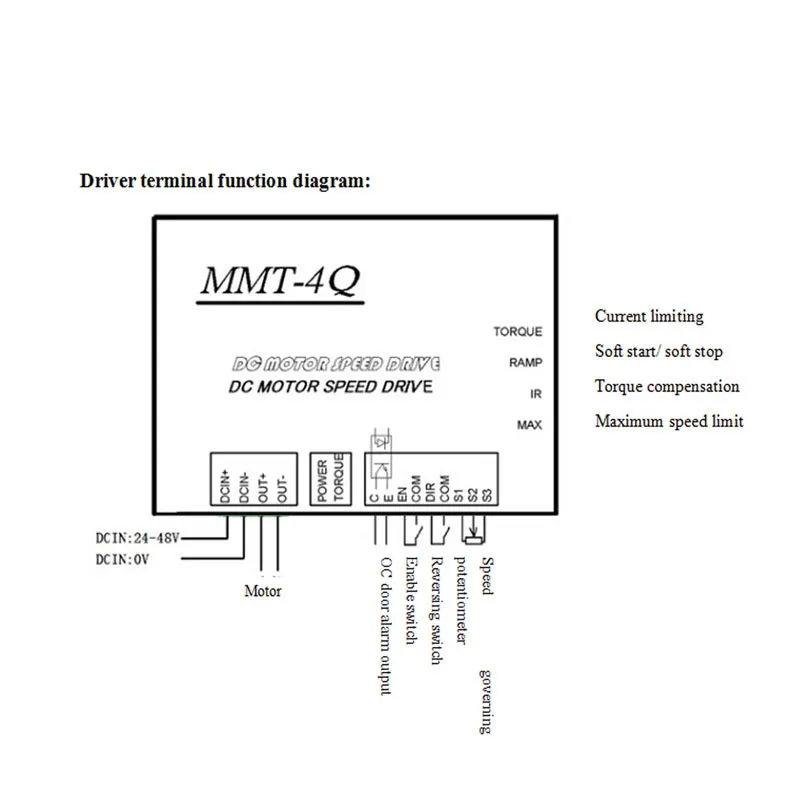
Description of control terminal’s functions:
1. EN (enable control)
During motor operation, simply connect/ disconnect EN with COM to control the start and stop of motor
Connect EN terminal with COM, EN terminal is effective, at this time regulate external speed potentiometer and motor is in normal operation.
EN terminal suspends in the air or is not connected, EN terminal is invalid; circuit of controller is blocked and motor stops.
2. DIR (direction control)
During motor operation, simply connect/ disconnect EN with COM to reverse the motor rotation. It doesn’t need external reversing contactor and will not result in electric motor parts or other components overheating or burning down.
Connect DIR terminal with COM, DIR terminal is effective, motor is in negative rotation.
DIR terminal suspends in the air or is not connected, DIR terminal is invalid; motor is in positive rotation (runs in opposite direction as above mentioned).
3. C E (OC door alarm output)
The internal design of “OC door alarm output” is that over-current signal is transmitted through an opto-coupler to give alarms. When over-current is detected on the controller, over-current signal will be immediately sent to diode of opto-coupler for break over and then transmitted to C, E ports. The client can wire as their own requirements, as shown in Figure 1, connect to over-current indicator,
Figure 2, relay actuation after over-current to give alarms.
Internal wiring diagram of “OC door alarm output” is shown as follows: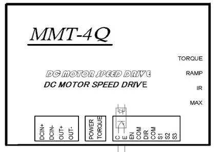
OC door alarm output
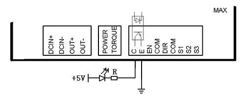
Alarm indicator output
Figure 1: Wiring description of alarm indicator output
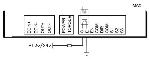
Relay coil
Figure 2: Wiring description of alarm relay output
4. S1 S2 S3 signal output terminal
Such controller has two control modes of external speed potentiometer control and external analog quantity input. Description of various terminals is as follows:
S1 Terminal: external power+10V ,
S2 Terminal: signal input terminal
S3 Terminal: GND (grounded).
4.1 When external speed potentiometer control is used, S1, S2, S3 terminals shall be connected with external potentiometer as shown in VI. Driver terminal function diagram to regulate external potentiometer for speed governing
4.2 When external analog quantity input control is used, speed can be controlled through S2 and S3 input, both 0-5V and 0-10V are OK.
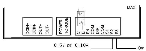
Description of indicator:
1. POWER (Green) power indicator
If the controller is charged, this indicator lights up to indicate that controller is under normal operation.
2. TORQUE (Red) over-current indicator turns red to indicate that output current of the controller exceeds client’s preset current, and the controller will automatically limit the output current to such value.
Regulation description of functional potentiometer:
MAX (maximum revolving speed limit)
It is used for limiting motor’s maximum revolving speed. Increase in clockwise rotation and decrease in counterclockwise rotation.
IR (Torque compensation)
Regulate “IR” enable motor work under different loads and keep revolving speed constant (normally factory default is 0), Increase in clockwise rotation and decrease in counterclockwise rotation.
RAMP (soft start/ stop)
Regulate “RAMP” to set motor’s starting and stopping time (1-20 S). Increase in clockwise rotation.
TORQUE (current limit regulation)
Regulate “TORQUE” to set over-current protection value of the controller; regulating range is 0-20A, Increase in clockwise rotation and decrease in counterclockwise rotation. When reaches over-current limit value, over-current indicator (Red) lights constantly and current is be limited to such value, at this time, continue to regulate the external potentiometer, current value is invariant( i.e. amplitude limiting).
24V PWM brushed dc motor controller DC24/20BL-4Q02 FORWARD&REVERSE
| Model | DC24/20BL-4Q02 |
| Max coutinuous current | 10A |
| Volt frange | 24-48vdc |
| Max current | 20A |
| Control mode | 0-10V、0-5V、PWM |
| Tempreture | -10℃-50℃ |
| Protection Grade | IP20 |
| Weight | 0.25kg |
| Dimension | 112*76*33 mm |
| Suitable | PM brush dc motor 300w |
| Application | Medical Equipment, welding, electric stooter |
13. Leakage current: ≤ 0.9 mA
Description of control terminal’s functions:
1. EN (enable control)
During motor operation, simply connect/ disconnect EN with COM to control the start and stop of motor
Connect EN terminal with COM, EN terminal is effective, at this time regulate external speed potentiometer and motor is in normal operation.
EN terminal suspends in the air or is not connected, EN terminal is invalid; circuit of controller is blocked and motor stops.
2. DIR (direction control)
During motor operation, simply connect/ disconnect EN with COM to reverse the motor rotation. It doesn’t need external reversing contactor and will not result in electric motor parts or other components overheating or burning down.
Connect DIR terminal with COM, DIR terminal is effective, motor is in negative rotation.
DIR terminal suspends in the air or is not connected, DIR terminal is invalid; motor is in positive rotation (runs in opposite direction as above mentioned).
3. C E (OC door alarm output)
The internal design of “OC door alarm output” is that over-current signal is transmitted through an opto-coupler to give alarms. When over-current is detected on the controller, over-current signal will be immediately sent to diode of opto-coupler for break over and then transmitted to C, E ports. The client can wire as their own requirements, as shown in Figure 1, connect to over-current indicator,
Figure 2, relay actuation after over-current to give alarms.
Internal wiring diagram of “OC door alarm output” is shown as follows:
OC door alarm output
Alarm indicator output
Figure 1: Wiring description of alarm indicator output
Relay coil
Figure 2: Wiring description of alarm relay output
4. S1 S2 S3 signal output terminal
Such controller has two control modes of external speed potentiometer control and external analog quantity input. Description of various terminals is as follows:
S1 Terminal: external power+10V ,
S2 Terminal: signal input terminal
S3 Terminal: GND (grounded).
4.1 When external speed potentiometer control is used, S1, S2, S3 terminals shall be connected with external potentiometer as shown in VI. Driver terminal function diagram to regulate external potentiometer for speed governing
4.2 When external analog quantity input control is used, speed can be controlled through S2 and S3 input, both 0-5V and 0-10V are OK.
Description of indicator:
1. POWER (Green) power indicator
If the controller is charged, this indicator lights up to indicate that controller is under normal operation.
2. TORQUE (Red) over-current indicator turns red to indicate that output current of the controller exceeds client’s preset current, and the controller will automatically limit the output current to such value.
Regulation description of functional potentiometer:
MAX (maximum revolving speed limit)
It is used for limiting motor’s maximum revolving speed. Increase in clockwise rotation and decrease in counterclockwise rotation.
IR (Torque compensation)
Regulate “IR” enable motor work under different loads and keep revolving speed constant (normally factory default is 0), Increase in clockwise rotation and decrease in counterclockwise rotation.
RAMP (soft start/ stop)
Regulate “RAMP” to set motor’s starting and stopping time (1-20 S). Increase in clockwise rotation.
TORQUE (current limit regulation)
Regulate “TORQUE” to set over-current protection value of the controller; regulating range is 0-20A, Increase in clockwise rotation and decrease in counterclockwise rotation. When reaches over-current limit value, over-current indicator (Red) lights constantly and current is be limited to such value, at this time, continue to regulate the external potentiometer, current value is invariant( i.e. amplitude limiting).
