- All
- Product Name
- Product Keyword
- Product Model
- Product Summary
- Product Description
- Multi Field Search
 |


| Quantity: | |
|---|---|
DC24RT15BL
Keya
DC24RT15BL
Four-Quadrant Reversible Regenerative Braking PWM DC Motor Controller DC24RT15BL
This motor controller is low voltage, four-quadrant regeneration and pulse-width modulation speed controlling system. The MCU (Microcontroller Unit) intelligent control makes quick response speed, smooth running, reliable operation and complete proportions, etc.
◆ PWM( pulse width modulation)
The PWM makes motor low noise, high efficiency and little maintenance. Service life of DC motor can be fatherly increased.
◆ Four-quadrant regeneration in operating mode.
◆ Regenerative braking function
External directional (or reversing) contactor is not required and components or parts of motor can be protected from superheated or burnout.
◆ Enable/Brake/Reversing terminal
One of above functions can be achieved with help of passive switching value or open (or broken) circuit of transistor collector.
◆ Status Light
Power light and various fault warning lights make the status of motor controller visible.
◆ Speed value of Forward or Reverse can be set respectively.
◆ Value of output current can be set.
◆ Value of brake current can be set.
◆ Torque compensation
◆ Double closed loop PI regulation(Voltage and current)
◆ Standard analog signal
Analog quantity (0-5V) or potentiometers are suitable for controlling.
◆ Overvoltage or under voltage protection
◆ Overheating protection
II.Technical performance
PWM (pulse width modulation)
Speed ratio: 1:80
Speed control mode: potentiometer (10KΩ/2W)
Input impedance:≥50K
Speed accuracy: 1 %
Soft start time: 0.2-20 seconds
Ambient temperature: --10℃~+60℃
Ambient humidity: Relative humidity≤80RH (non condensing)
Instantaneous short circuit protection (50us)
Outline dimension: 127*34*75mm
Weight: 380g
Adopted SMT technology makes motor controller small size.
Current setting and limiting protection
ACCEL/DECEL
Quick stopping
Huge torque at low speed start up.
Remote start (run) and stop
This motor controller is suitable for lanthanide (rare earth)motor, permanent magnet motor and separately excited motor.
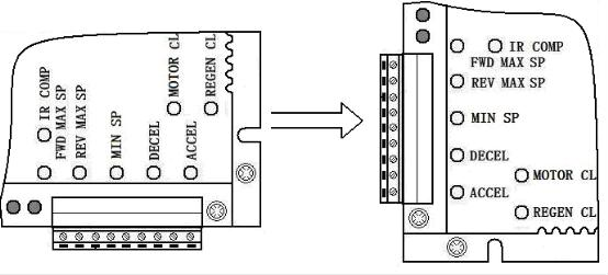
Outline dimension(Unit:mm)

4. Wiring requirements:
1. Before wiring, the power supply must be disconnected.
2. Choose insulated conductors and shielding cables which are capable of motor controller’s Voltage and current. Specification of power input wire of motor controller and connecting Wire of motor must meet the following requirements in chart 2.
3. Use shielding cables to connect signal wire with control wires, separate them from power input wire and power output wire during wiring.
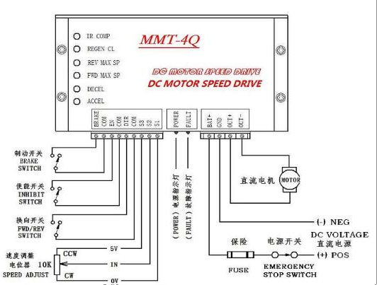
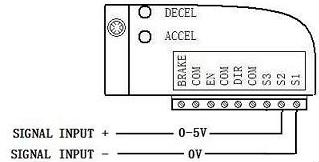
Diagrammatic sketch of connecting terminal
Connection about fuse, power switch and motor:
1. One piece of quick-blowing fuse and power supply emergency switch must be added between power input port of motor controller and power supply in sake of emergency power off in some case. (See Figure 3)
Note: When select quick-blowing fuse and power supply emergency switch, the rated current value of switch should be equal or greater than 150-200% value of rated current of applied motor.
2. Connection of motor
OUT+ and OUT - terminals connected motor controller with DC motor are in Figure 3,please see it.
The voltages from motor controller are transferred to applied motor through connecting terminals of OUT+ and OUT. When OUT+ terminal is with positive polarity and OUT – terminal is connected with negative polarity, motor will rotate in clockwise while if connected inversely, motor will rotate in counter clockwise (See Figure 4). Just convert the Reversing switch (FWD/REV) to let motor rotate in clockwise.
Note: Please ensure the rated voltage value of motor must match with output voltage value of motor controller.
Connection about speed control potentiometer:
 The connecting wire of speed control potentiometer should be away from conductors of power input terminal and output in sake for reducing unnecessary interfere of electronic signals. The length of connecting wire should be shortening as far as possble. If the length is over 0.5m, the shielding wire is recommended.
Function and connection about control terminal:
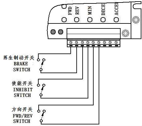
1. BRAKE:Regenerative braking control terminal:
Regenerative braking control: When quick stopping of motor is required, this function is suitable. Close brake switch, motor controller rapidly brakes motor’s speed by the way of regenerative braking then make motor stop immediately.
2. EN:Enable control terminal:
Enable control: Control the start and stop of motor
Open external enable switch, motor controller will automatically lock in internal circuit and make motor stops.
Close external enable switch, motor will start to rotate at the speed value set by potentiometer or input analog signals.
Note: A. When regenerative braking, the motor’s stop time is decided by set value of brake current (“REGEN CL” potentiometer set current) or set value of soft stop (“DECEL” potentiometer set soft stop time).
E.g. If the set value of brake current(“REGENCL” potentiometer set current ) is high and the set value of soft stop time(“DECEL” potentiometer set soft stop time) is low, the motor’s brake time will be shorten.
B. When close brake switch, rotate speed value after braking is decided by set value of “MIN SP” potentiometer (means Min speed). E.g. If the “MIN SP” potentiometer set the value “0”, then after brake, the motor rotate speed will be “0”. If the “MIN SP” potentiometer set the value “N”, then after brake, the motor rotate speed will be “N”.
3. DIR: Reversing (Direction) control terminal:
The reversing control of motor: Rotation direction can be easily get through open or close reversing switch.
10.Control mode and connection about external analog quantity:
1. Connection of function control signal’s switching analog value Photo couplers or open collector control:

Connection of speed control’s analog quantity
Introduction and setting of adjustable potentiometer:
1. “ACCEL” potentiometer (Set soft start time):
Adjust “ACCEL” potentiometer to set ramp up from initial speed value to setting speed value (it means acceleration time, the time can be adjusted between 0.2 seconds and 20 seconds).Please see the Figure 11.

Note: Adjust this potentiometer in counter-clockwise to shorten soft start time while adjust this potentiometer in clockwise to prolong soft start time.
Figure 11 2.“DECEL” potentiometer( Set soft stop time ):
Adjust “DECEL” potentiometer to set ramp down from Max.speed value to Min.speed value (it means deceleration time, the time can be adjusted between 0.2 seconds and 20 seconds). Note: Adjust this potentiometer in counter-clockwise to shorten soft stop time while adjust this potentiometer in clockwise to prolong soft stop time.
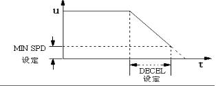
Figure 12
Four-Quadrant Reversible Regenerative Braking PWM DC Motor Controller DC24RT15BL
This motor controller is low voltage, four-quadrant regeneration and pulse-width modulation speed controlling system. The MCU (Microcontroller Unit) intelligent control makes quick response speed, smooth running, reliable operation and complete proportions, etc.
◆ PWM( pulse width modulation)
The PWM makes motor low noise, high efficiency and little maintenance. Service life of DC motor can be fatherly increased.
◆ Four-quadrant regeneration in operating mode.
◆ Regenerative braking function
External directional (or reversing) contactor is not required and components or parts of motor can be protected from superheated or burnout.
◆ Enable/Brake/Reversing terminal
One of above functions can be achieved with help of passive switching value or open (or broken) circuit of transistor collector.
◆ Status Light
Power light and various fault warning lights make the status of motor controller visible.
◆ Speed value of Forward or Reverse can be set respectively.
◆ Value of output current can be set.
◆ Value of brake current can be set.
◆ Torque compensation
◆ Double closed loop PI regulation(Voltage and current)
◆ Standard analog signal
Analog quantity (0-5V) or potentiometers are suitable for controlling.
◆ Overvoltage or under voltage protection
◆ Overheating protection
II.Technical performance
PWM (pulse width modulation)
Speed ratio: 1:80
Speed control mode: potentiometer (10KΩ/2W)
Input impedance:≥50K
Speed accuracy: 1 %
Soft start time: 0.2-20 seconds
Ambient temperature: --10℃~+60℃
Ambient humidity: Relative humidity≤80RH (non condensing)
Instantaneous short circuit protection (50us)
Outline dimension: 127*34*75mm
Weight: 380g
Adopted SMT technology makes motor controller small size.
Current setting and limiting protection
ACCEL/DECEL
Quick stopping
Huge torque at low speed start up.
Remote start (run) and stop
This motor controller is suitable for lanthanide (rare earth)motor, permanent magnet motor and separately excited motor.
Outline dimension(Unit:mm)
4. Wiring requirements:
1. Before wiring, the power supply must be disconnected.
2. Choose insulated conductors and shielding cables which are capable of motor controller’s Voltage and current. Specification of power input wire of motor controller and connecting Wire of motor must meet the following requirements in chart 2.
3. Use shielding cables to connect signal wire with control wires, separate them from power input wire and power output wire during wiring.
Diagrammatic sketch of connecting terminal
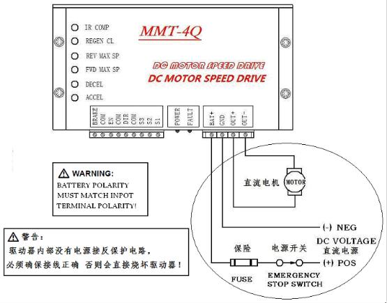
Connection about fuse, power switch and motor:
1. One piece of quick-blowing fuse and power supply emergency switch must be added between power input port of motor controller and power supply in sake of emergency power off in some case. (See Figure 3)
Note: When select quick-blowing fuse and power supply emergency switch, the rated current value of switch should be equal or greater than 150-200% value of rated current of applied motor.
2. Connection of motor
OUT+ and OUT - terminals connected motor controller with DC motor are in Figure 3,please see it.
The voltages from motor controller are transferred to applied motor through connecting terminals of OUT+ and OUT. When OUT+ terminal is with positive polarity and OUT – terminal is connected with negative polarity, motor will rotate in clockwise while if connected inversely, motor will rotate in counter clockwise (See Figure 4). Just convert the Reversing switch (FWD/REV) to let motor rotate in clockwise.
Note: Please ensure the rated voltage value of motor must match with output voltage value of motor controller.
Connection about speed control potentiometer:
The connecting wire of speed control potentiometer should be away from conductors of power input terminal and output in sake for reducing unnecessary interfere of electronic signals. The length of connecting wire should be shortening as far as possble. If the length is over 0.5m, the shielding wire is recommended.
Function and connection about control terminal:
1. BRAKE:Regenerative braking control terminal:
Regenerative braking control: When quick stopping of motor is required, this function is suitable. Close brake switch, motor controller rapidly brakes motor’s speed by the way of regenerative braking then make motor stop immediately.
2. EN:Enable control terminal:
Enable control: Control the start and stop of motor
Open external enable switch, motor controller will automatically lock in internal circuit and make motor stops.
Close external enable switch, motor will start to rotate at the speed value set by potentiometer or input analog signals.
Note: A. When regenerative braking, the motor’s stop time is decided by set value of brake current (“REGEN CL” potentiometer set current) or set value of soft stop (“DECEL” potentiometer set soft stop time).
E.g. If the set value of brake current(“REGENCL” potentiometer set current ) is high and the set value of soft stop time(“DECEL” potentiometer set soft stop time) is low, the motor’s brake time will be shorten.
B. When close brake switch, rotate speed value after braking is decided by set value of “MIN SP” potentiometer (means Min speed). E.g. If the “MIN SP” potentiometer set the value “0”, then after brake, the motor rotate speed will be “0”. If the “MIN SP” potentiometer set the value “N”, then after brake, the motor rotate speed will be “N”.
3. DIR: Reversing (Direction) control terminal:
The reversing control of motor: Rotation direction can be easily get through open or close reversing switch.
10.Control mode and connection about external analog quantity:
1. Connection of function control signal’s switching analog value Photo couplers or open collector control:
Connection of speed control’s analog quantity
Introduction and setting of adjustable potentiometer:
1. “ACCEL” potentiometer (Set soft start time):
Adjust “ACCEL” potentiometer to set ramp up from initial speed value to setting speed value (it means acceleration time, the time can be adjusted between 0.2 seconds and 20 seconds).Please see the Figure 11.
Note: Adjust this potentiometer in counter-clockwise to shorten soft start time while adjust this potentiometer in clockwise to prolong soft start time.
Figure 11 2.“DECEL” potentiometer( Set soft stop time ):
Adjust “DECEL” potentiometer to set ramp down from Max.speed value to Min.speed value (it means deceleration time, the time can be adjusted between 0.2 seconds and 20 seconds). Note: Adjust this potentiometer in counter-clockwise to shorten soft stop time while adjust this potentiometer in clockwise to prolong soft stop time.
Figure 12
